Your Content Goes Here
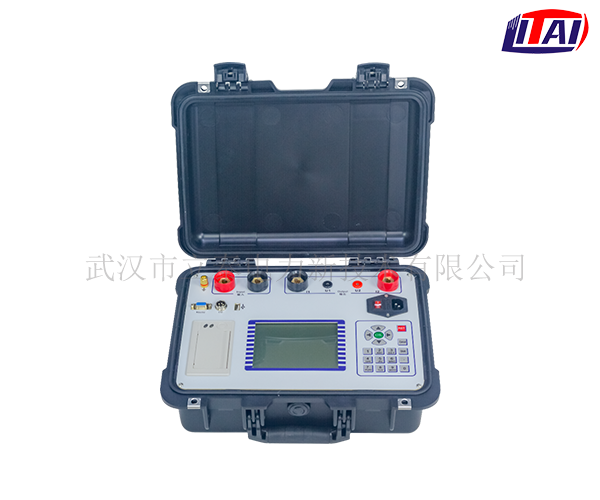
Ac impedance test generator rotor. Wiring Diagram. It is a special instrument for judging whether the generator rotor winding has inter-turn short circuit. It can measure the voltage, current, impedance, power, speed, etc. of the rotor winding automatically and manually (one-way or two-way) parameter.
The generator rotor AC impedance tester adopts advanced high-speed microprocessor technology, which is more powerful, superior in performance, and more convenient to use. It has the characteristics of high reliability, easy operation, high test accuracy, compactness and lightness.
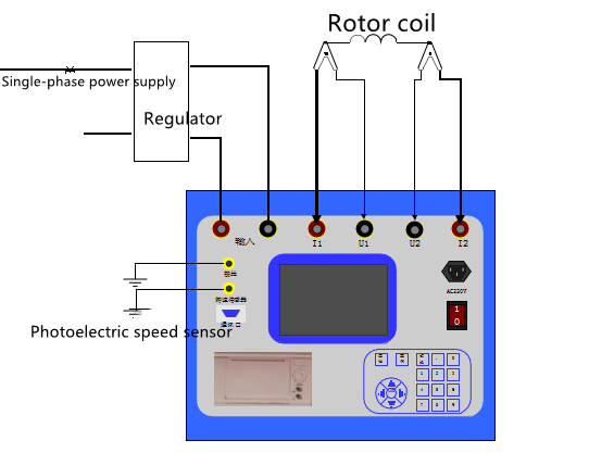
The wiring diagram of the generator rotor AC impedance tester is as follows:
Wiring diagram of generator rotor AC impedance tester
Note: A single-phase voltage regulator is used during the test, so zero-sequence current will be generated in the on-site power supply system. Therefore, in order to avoid zero-sequence protection tripping, it is best to use an isolated voltage regulator.


