Your Content Goes Here
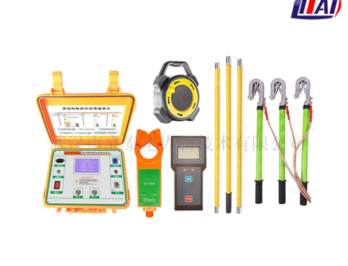
The use method and test procedure of the high and low voltage current transformer ratio tester. The high and low voltage current transformer ratio tester is a new type of electricity inspection equipment for high-voltage metering users.It also belongs to voltage and turn ratio test of transformer.
It can detect the transformation ratio and polarity of current transformers used in metering devices of 35KV and below under the condition of uninterrupted power and no line changes. It can also detect the consistency of the primary and secondary phases of the transformer, thereby effectively preventing high-voltage metering users Take measures to replace high and low voltage current transformers or current transformer nameplates and change the polarity of the secondary line or the phase difference to achieve low billing.
The use method and test steps of the high and low voltage current transformer ratio tester are as follows:
Test preparation:
1. Check the appearance of each part of the instrument, and proceed to the next step only if there is no damage, deformation, dirt, or water stains;
2. Turn on the power switch, observe the voltage value of each part of the battery in the LCD screen and the percentage of remaining power to see if the battery power is sufficient.
3. Check whether the operation of the insulating rod is normal, whether the function of the locking part of each rod is normal, whether it can be flexibly locked and loosened, and can be used after normal.
The use method and test procedure of the high and low voltage current transformer ratio tester:
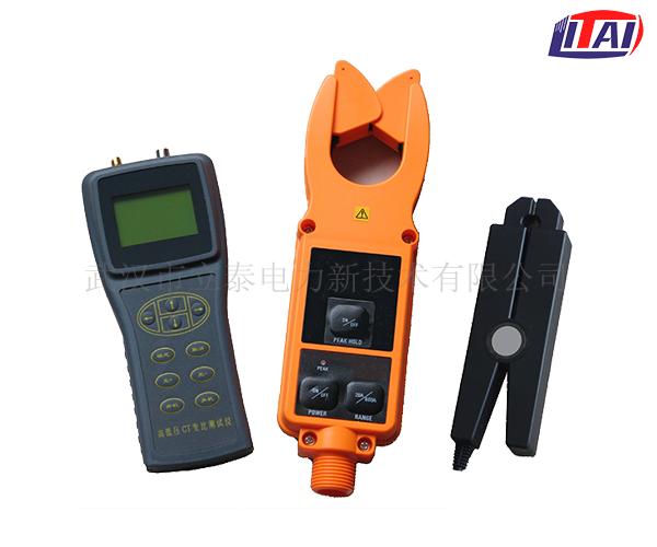
1. Connect the low-voltage clamp meter to the host well, and pay attention to locking the interface to prevent open circuit;
2. Connect the host antenna to ensure the quality of wireless communication (if the distance between the high and low voltage measured points is very close and there are no obstacles, you don’t need to connect the antenna);
3. Turn on the power of the host and select to enter the “transformation ratio measurement” function screen;
4. Clip the low-voltage clamp meter to any one of the secondary side wires of the transformer under test, so that the current flows in from the direction marked with the inflow end of the clamp meter, and also pay attention to the good closing of the clamp; Display the amplitude of the secondary current;
4. Connect the high-voltage clamp meter to the insulating rod, adjust the length of the insulating rod according to the height of the line to be tested, and ensure that the connection of each rod is indeed locked;
5. Gently push the insulating rod upwards to clamp the high-voltage clamp meter on the primary conductor of the transformer under test, and pay attention to the direction of current flow and the good closure of the jaws;
6. Read the test results of the host;
7. Pull down the insulating rod to separate the high-voltage clamp meter from the tested circuit. The action should be gentle and not strong to prevent damage to the mechanical structure;
8. Put away the insulating rod, turn off the power of the high-voltage clamp meter, and remove it from the insulating rod;
9. Remove the low-voltage clamp meter from the secondary line, and then remove the low-voltage clamp meter from the host;
9. Turn off the power of the host and take off the antenna;
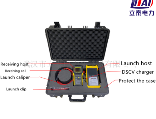
10. Receive all accessories into the packing box, and the test is completed.
The use method and test procedure of the high and low voltage current transformer ratio tester. The high and low voltage current transformer ratio tester is easy to use, easy to carry, and has a high safety factor. It is a rare detection tool for electricity inspectors. When using the high and low voltage current transformer ratio tester, you need to use the two methods and procedures together. For specific operation items, please follow the instructions of the on-site high and low voltage current transformer ratio tester.


