Your Content Goes Here
How to test protective relays
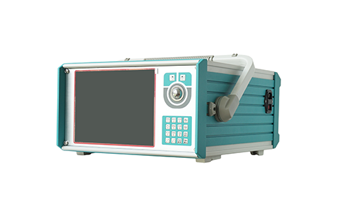
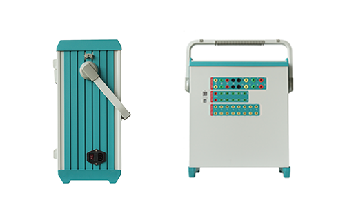
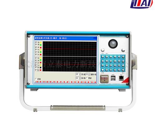
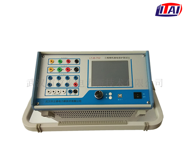
The microcomputer relay protection tester has been widely used in various fields such as line protection, main transformer differential protection, excitation control and so on. Integrated substation automation has become the mainstream. The relay protection tester is an important test instrument to ensure the safe and reliable operation of the power system. The relay protection tester also has its own working principle.
The working principle of the relay protection tester is as follows: The relay protection tester is divided into two circuits: the main circuit and the auxiliary circuit. The main circuit is adjusted by a large knob, and the auxiliary circuit is adjusted by a small knob. The main circuit is adjusted by the “output selection” button on the panel. The switch controls various quantities of its output, and each time one output is switched, the digital voltage/current meter on the instrument can automatically monitor its output value. The auxiliary circuit is controlled by the output switch to directly adjust the output, and the measurement can be measured by an external multimeter.
1) The working principle of the main circuit of the relay protection tester
The input AC220V power supply enters the dual carbon brush voltage regulator T1 input terminal through the output control relay K1 through the insurance, and the power adjusted by the T1 large knob enters the isolation transformer T2. The booster has three taps for output, one tap is AC0-250V output , The rated current is 3A; the output voltage of this tap can output 0-350V DC voltage after rectification and filtering; the second one is 15V (10A), the tap is controlled by a sensor and a relay to output 0-10A AC current, all the way through a resistor Output 0-500mA AC current, one way can output 0-10A or 0-500mA DC current through relay conversion; the second tap is 10V (100A) high current terminal, this tap passes through the primary side of the sensor and directly outputs 100A current, this loop The load capacity is strong, but the output is slightly overloaded, and it cannot be in a high current state for a long time.
2) The working principle of the auxiliary circuit of the relay protection test instrument
The auxiliary circuit of the relay protection test instrument has the same principle as the main circuit. The AC220V power supply is insured into the double carbon brush voltage regulator T1 small knob to adjust the voltage, and the isolation transformer T4 can directly adjust the output 0-20V or 0-250V AC voltage or 0-350V DC voltage, the rated current of this loop is 1A. Press the “output control” switch of the auxiliary circuit and adjust the small knob to output.
Modern microcomputer relay protection testers can be divided into two forms. One is the use of traditional OCL power amplifiers, which are large in size and weigh about 25Kg, which is relatively heavy. The power amplifier tube works in the amplification area. It is easy to be damaged after a long time and has a dynamic range. Narrow, not high precision. The other is to use a switching power supply. The power amplifier uses a digital power amplifier, which is small in size, light in weight and high in efficiency. It is an upgraded version of the traditional relay protection tester and has been maturely put into use.

