Project Description
Product Features:
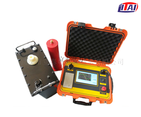
Advanced technology: adopting digital frequency conversion technology, microcomputer control, fully automated testing processes such as step-up, step-down, measurement, protection, etc.
Convenient operation: simple wiring, fool-proof operation.
Comprehensive protection: multiple protections (overvoltage protection, high and low voltage side overcurrent protection), rapid action (action time ≤ 10ms), the instrument is safe and reliable.
Safe and reliable: The controller and the high-voltage generator are connected at low voltage, controlled by photoelectric, and are safe and reliable to use.
High and low voltage closed-loop negative feedback control circuit is adopted, and the output has no capacity increase effect.
The high-voltage withstand voltage test of electrical equipment is one of the most important items specified in the “Insulation Preventive Test”. It also belongs to high frequency voltage generator. Withstand voltage test can be divided into AC withstand voltage test and DC withstand voltage test. AC withstand voltage test can be divided into power frequency, frequency conversion and 0.1Hz ultra-low frequency test technology. Among them, 0.1Hz ultra-low frequency technology is the most new technology, which is current Technology recommended by the International Electrotechnical Commission.
Our new generation series of ultra-low frequency high-voltage generators are core products independently developed by adopting the latest American technology. It adopts 7-inch touch screen, the latest ARM7 single-chip microcomputer, high-speed AD acquisition circuit, and is equipped with background management software. It overcomes many shortcomings of similar domestic products (see Table 1), and the cost performance is much higher than similar imported products. It is especially suitable for electrical equipment with large insulation equivalent capacitance (such as: power cables, power capacitors, large and medium-sized generators and Electric motor, etc.) withstand voltage test, in line with the 2004 national power industry standard “Ultra-low frequency high voltage generator general technical conditions DL/T849.4-2004” requirements.
Table 1 Comparison of mechanical and electronic performance of 0.1Hz withstand voltage test equipment
| 0.1HZ withstand voltage equipment type | High voltage control method | High voltage waveform | Energy saving | noise | Mechanical life | Electric life |
|---|---|---|---|---|---|---|
| mechanical | High voltage mechanical switch to switch polarity | Fang Bo | No energy saving: Use high-power resistors to consume excess energy | high | short | short |
| Electronic | High voltage electronic switch to switch polarity | Sine wave | Energy-saving: return excess power to the grid | slight | no | long |
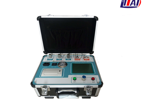
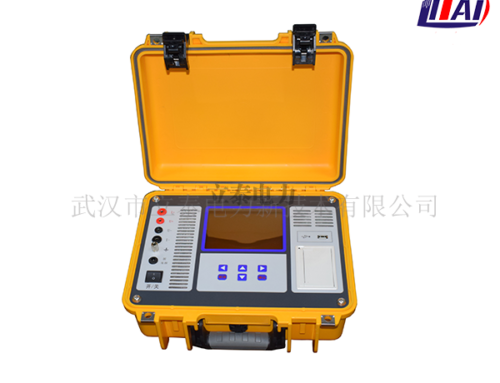
Complete configuration: capacitive touch screen, LCD Chinese character display, automatic storage, automatic printing.
Large test range: 0.1Hz, 0.05Hz and 0.02Hz multiple frequency options, large test range.
Small size and light weight: very conducive to outdoor operations.
| 1. Output rated voltage: | See Table 3 | |
|---|---|---|
| 2. Output frequency: | 0.1Hz, 0.05Hz, 0.02Hz | |
| 3. Load capacity: | 0.1Hz max 1.1µF | |
| 0.05Hz max 2.2µF | ||
| 0.02Hz max 5.5µF | ||
| 4. Measurement accuracy: | 3% | |
| 5. Voltage positive and negative peak error: | ≤3% | |
| 6. Distortion degree of voltage waveform: | ≤5% | |
| 7. Conditions of use: | Indoor and outdoor; temperature: -10℃~+40℃; humidity: ≤85%RH | |
| 8. Power fuse: | See Table 3 | |
| 9. Power supply: | Voltage 220V±5%, 50±5Hz | |
| Producr name | Rated voltage | Load capacity | Power fuse | Product structure and weight | |
|---|---|---|---|---|---|
| -30/1.1 | 30kv (peak value) | 0.1Hz,≤1.1µF | 8A | Controller: 6kg Booster: 20kg | |
| 0.05Hz,≤2.2µF | |||||
| 0.02Hz,≤5.5µF | |||||
| -50/1.1 | 50kv (peak value) | 0.1Hz,≤1.1µF | 10A | Controller: 6kg Booster: 45kg | |
| 0.05Hz,≤2.2µF | |||||
| 0.02Hz,≤5.5µF | |||||
| 0.1Hz,≤1.1µF | |||||
| -80/0.5 | 80kv(peak value) | 0.05Hz,≤2.2µF | 20A | Controller: 4kg Booster: 50kg | |
11. When using the product of appropriate specifications according to the tested object, the capacitance of the test product shall not exceed the rated capacitance of the instrument. If the capacitance of the test product is too small, it will affect the output waveform. If it is less than 0.05 µF, the instrument will not be able to output normally. At this time, a 0.05 µF capacitor (provided by our company) can be connected in parallel for auxiliary output. Refer to Table 4 for the estimation of the electric capacity of common electrical equipment.
Table 4 Single-phase ground capacity of different types of generators
| 汽轮发电机 | Steam turbine generator | Hydrogenerator | |||||||
|---|---|---|---|---|---|---|---|---|---|
| 发电机容量(MW) | 200 | Generator capacity (MW) | 200 | 300 | 600 | 85 | 125-150 | 300 | 400 |
| 单相对地电容(υF) | 0.198 | Single phase to ground capacitance (υF) | 0.198 | 0.18-0.26 | 0.31-0.34 | 0.69 | 1.8-1.9 | 1.7-2.5 | 2.0-2.5 |
| Serial number | Product name | Qutantity | Unit |
|---|---|---|---|
| 1 | Controller | 1 | station |
| 2 | Booster | 1 | station |
| 3 | High voltage connection cable | 2 | root |
| 4 | Dedicated low voltage connection cable | 1 | root |
| 5 | power cable | 1 | root |
| 6 | Discharge rod | 1 | root |
| 7 | Ground wire | 1 | root |
| 8 | Compensation capacitor | 1 | only |
| 9 | Fuse | 4 | only |
| 10 | printer paper | 2 | volume |
| 11 | Manual | 1 | Share |
| 12 | Packing List | 1 | Share |
| 13 | experimental report | 1 | Share |

